The performance of high-precision optical systems is often bottlenecked by geometric aberrations. Enter aspheric and freeform optics—these complex shapes can drastically reduce or even eliminate these aberrations, all while cutting down the number of lenses needed, shrinking the system's size, and reducing its overall weight.
While modern manufacturing techniques have made creating these high-precision freeform surfaces a reality, the real challenge lies in measuring them. To successfully manufacture and apply these optics, we need the right metrology techniques: tools that are highly precise, versatile, non-contact, capable of handling large measuring volumes, and incredibly fast. Back in the early 2000s, however, these technologies were far from mature.

The Challenge: When Holding and Measuring Collide
Traditionally, manufacturing equipment relies on a "C-frame" structure, physically connecting the cutting tool and the workpiece at a specific target point. In this setup, the machine's overall stiffness is dictated by its structural loop, while positional information is provided by its metrology loop.
The problem? In three-dimensional space, these loops usually overlap. As a result, the forces and thermal changes within the structural loop can directly cause measurement errors in the metrology loop (see Figure 1). For high-tech, ultra-precision systems looking to minimize uncertainty, the golden rule is to physically separate these loops and assign them to entirely different hardware components.

| Image 1. A schematic of a traditional manufacturing machine. The structural loop (orange), metrology loop (yellow), and force path (red) often overlap, which can lead to measurement errors in the metrology loop [2]. | Image 2. Error motions caused by mechanical or thermal loads, as well as manufacturing tolerances within the metrology loop, lead to measurement errors (uncertainty). The Solution: A New Metrology Architecture |
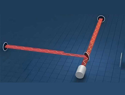
To conquer the challenge of measuring freeform optics, researchers developed a non-contact measurement machine [1] utilizing a cylindrical scanning configuration paired with an optical distance probe. This probe is a game-changer: it is non-contact, highly versatile, and lightning-fast. Armed with an extended measurement range (operating on the millimeter scale), the system can rapidly measure circular tracks across a freeform surface with minimal dynamic response.
The true brilliance of this system lies in its completely independent Metrology Frame. The positions of both the probe [3] and the workpiece are measured relative to this isolated, stress-free frame (see Figure 3). By doing this, the system virtually eliminates the stage errors that typically plague the metrology loop.
Furthermore, the probe is intentionally kept perpendicular to the local best-fit aspheric surface of the optic. This clever geometric design drastically reduces the system's sensitivity to tangential (sideways) positioning errors, allowing the metrology system to effectively perform high-precision 2D measurements.

| Image 3. Schematic of the machine concept, featuring a non-contact, long-range optical probe [3] used to measure a part that rotates on a spindle and moves across a 2D plane via a ZR motion system. | Image 4. A complete metrology loop based on measuring 6 critical in-plane parameters: the probe length, the R and Z positions of the ψ-axis measured by laser interferometers, and the R and Z positions alongside the orientation of the rotary stage, measured by capacitive probes [1]. |
Achieving Nanometer Precision
This advanced metrology system actively measures the probe's position relative to the workpiece across six critical directions within the measurement plane. Displacement between the probe and a reference mirror located on the upper metrology frame is tracked by focusing both vertical and horizontal laser interferometers directly onto the ψ-axis rotor.
Because the probe tip is designed with reduced tangential sensitivity, the system successfully satisfies the strict Abbe Principle (a fundamental rule in precision engineering stating that the measuring axis should be collinear with the displacement axis to avoid alignment errors).
When it came to building the frame, engineers chose Silicon Carbide (SiC). Why? Because SiC possesses extraordinary thermal and mechanical properties. Under expected thermal loads, this material ensures structural stability down to the nanometer scale. But the innovation doesn't stop at the hardware. Simulations of a multi-probe method demonstrated that the system could use advanced algorithms to decouple—or separate—the actual profile of the spindle reference edge from the spindle's own motion errors in real-time, achieving an uncertainty level in the sub-nanometer range.

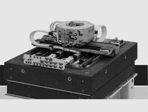
| Image 5. The laser interferometer system measuring the ψ-axis. | Image 6. The prototype implementation of the non-contact measurement machine for freeform optics [1]. |
Key Definitions
Structural Loop (= Stiffness Loop or Position Loop):
The physical assembly chain connecting one machine component to another,providing physical support and constraint for every element.
Metrology Loop (= Measurement Loop):
The shortest path carrying information about the relative positions of two or more measuring points. It consists of a series of solid objects linked by position-measuring sensors or calibrated sliding mechanisms.Force Path (= Load Path):
The assembly chain from one machine component to another responsible for transmitting forces (both static and dynamic).
Application:
A non-contact measurement machine dedicated to freeform optics.
Realization:
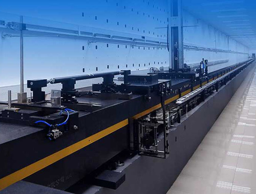
This concept gave birth to a prototype named NANOMEPHOS, which ultimately laid the technical foundation for the commercial NMF platform by Dutch United Instruments.
Core Principle:
Physically isolating the metrology loop from both the structural loop and the force path to drastically minimize measurement uncertainty.
References
[1] Henselmans, R., Non-contact measurement machine for freeform optics, PhD Thesis, Eindhoven University of Technology, Netherlands, April 2, 2009.
[2] Henselmans, R., Non-contact measurement machine for freeform optics, Design Principles Application Lecture Notes 4CM50, Eindhoven University of Technology, May 2021.
[3] Cacace, L.A., Optical distance sensor - tilt robust differential confocal measurement with millimeter range and nanometer uncertainty, PhD Thesis, Eindhoven University of Technology, Netherlands, December 1, 2009.