When evaluating the accuracy of a linear motion system, the spotlight usually falls on the positioning accuracy and repeatability of the driving mechanism. However, the true precision of a linear system is governed by a complex trio of factors:linear errors, angular errors, and the notorious Abbe error. Among these three, Abbe error is arguably the most elusive—it is incredibly difficult to measure, quantify, and prevent.Yet, in the realms of precision machining, metrology, and high-accuracy positioning, it is often the primary culprit behind compromised results.

It All Starts with Angular Errors.
At its core, Abbe error is born from a combination of angular errors within the motion system and the physical distance (the offset) between your "point of interest" (like a cutting tool or a payload) and the source of the error (such as a screw or a guide rail).
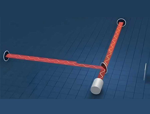
To understand this, let's look at the standard Cartesian coordinate system used in linear motion. It features three linear dimensions: the X, Y, and Z axes. For a single-axis linear stage, we typically treat the X-axis as the direction of travel, with the Y and Z axes sitting perpendicular to it. Beyond these three linear movements, there are also three rotational dimensions:pitch, roll, and yaw.
Angular errors are simply the unintended rotational movements a linear system makes around its three axes.

Imagine a system moving horizontally along the X-axis, as shown in the illustration above. Pitch is defined as rotation around the Y-axis, yaw is rotation around the Z-axis, and roll is rotation around the X-axis.
You might wonder, where do these pitch, roll, and yaw errors come from? Typically, they stem from microscopic imperfections in the guide rail system. However, mounting surfaces and assembly methods are also common suspects. For instance, an unevenly machined mounting base, loosely fastened components, or even differing thermal expansion coefficients between the system and its mounting surface can introduce angular errors that dwarf the inherent flaws of the linear guides themselves.
Crucially, these inaccuracies don't happen because the stage failed to travel the correct linear distance. They are the offspring of tiny, inherent tilts (pitch, roll, yaw) caused by bearing, mounting, or structural defects. Here is the kicker: these microscopic tilts are dramatically amplified as distance increases, resulting in a significant positional deviation at your actual target point. This amplification phenomenon is what we call the Abbe error.
Understanding and calculating the Abbe error is absolutely vital for anyone designing truly high-precision motion systems. It is particularly troublesome because it acts as a magnifying glass for angular errors that are otherwise microscopically small. The further your target is from the component causing the error—a distance known as the Abbe offset—the larger the error magnitude becomes.

In the illustration above, the Abbe offset is represented by h. The resulting Abbe error, δ, can be calculated using a simple trigonometric formula:
δ = h * tan θ
Named after the brilliant physicist Ernst Abbe, the Abbe error (sometimes referred to as the sine error) perfectly describes how angular errors are amplified by distance. To put this into perspective: if you are aiming at a point 1 meter away at a 90-degree angle, a mere 1-degree angular error translates to a positional deviation of over 1.745 centimeters. That equates to a massive 1.745% error in your distance measurement!
The mechanics of your system dictate its vulnerability. For cantilevered loads, the further the payload hangs away from the source of the angular error (usually a point on the guide rail or mounting surface), the more severe the Abbe error. In multi-axis setups (like gantry systems, Cartesian robots, or XY tables), the situation gets even more complex, as angular errors from each individual axis stack on top of one another.
Interestingly, compared to other multi-axis systems, XY tables are generally less susceptible to Abbe errors. This is mainly because their design minimizes cantilevered travel, and they typically operate with the payload safely centered directly over the Y-axis carriage.
In mechanical design, certain components are hyper-sensitive to angular inaccuracies. Take a lathe, for example. Even the slightest deviation in parallelism between the spindle axis and the tool's path along the machine bed can cause the machined part to develop a significant taper, resulting in a flawed, non-cylindrical shape.
So, how do we fight back? The golden rule for minimizing Abbe error is to use ultra-high-precision guide rails and ensure all mounting surfaces are flawlessly machined, preventing external errors from creeping into the system. Furthermore, keeping the payload as close to the system's center as possible effectively shrinks the Abbe offset, thereby minimizing the resulting error.
When it comes to measuring Abbe error accurately, a laser interferometer or fully independent optical equipment is the gold standard. However, since laser interferometers are cost-prohibitive and impractical for everyday applications, engineers often turn to linear encoders. For the most precise measurement in these scenarios, the encoder's readhead should be mounted directly at the point of interest (such as the cutting tool or the payload itself).

In a perfect, theoretical world, a motion table would glide flawlessly along its intended axis without a nanometer of deviation in any other dimension. In reality, errors haunt all six degrees of freedom. Errors along the X-axis are simply called "accuracy errors," while unwanted movements along the Y and Z axes are referred to as horizontal runout and vertical runout, respectively.
These three linear errors are constant; their value remains the exact same regardless of where you measure them. But angular errors—those pesky rotations—are a different beast entirely. Their linear impact continuously grows the further your measurement point moves away from the sliding stage.
A Real-World Example: Calculating Abbe Error in a Dual-Axis XZ System
To bring this theory into the real world, let's examine an LRQ XZ system. Imagine two linear stages mounted perpendicularly to each other using an AB164 bracket. The bottom stage handles the X-axis (horizontal movement), while the top stage handles the Z-axis (vertical movement). The setup looks like this:

Let's assume the vertical stage (Z-axis) has a travel of 150 mm, and the horizontal stage (X-axis) has a travel of 300 mm. The 300 mm LRQ linear stage (X-axis) comes with the following angular error specifications:
Pitch: 0.034° (Rotation around the Y-axis)
Roll: 0.015° (Rotation around the X-axis)
Yaw: 0.03° (Rotation around the Z-axis)
For this specific XZ application, pitch and roll are our biggest worries. Why? Because the physical offsets between the pitch/roll axes and our ultimate target point can be quite large.
In this configuration, the yaw offset (around the Z-axis) is relatively small and constant. Therefore, the yaw-induced Abbe error is noticeably smaller than those caused by pitch or roll, though it's still worth calculating. If absolute precision is required, a custom bracket could be used to further reduce this yaw offset by centering the Z-axis stage closer to the middle of the X-axis platform.
Let's focus on pitch error (rotation around the Y-axis). When the horizontal stage pitches, it causes the very top of the vertical LRQ stage to shift slightly along the X-axis. To quantify the impact of this error, we need to locate the actual position of both platform tops. Our point of interest is the top of the Z-axis stage. The worst-case scenario occurs when the Z-axis stage is fully extended to the top, maximizing the offset.
Referencing our 3D models and blueprints, we determine that the distance between the top center of the X-axis stage and the top center of the fully extended Z-axis stage is 212 mm. This critical distance is illustrated below:

Let's calculate the Abbe error along the X-axis (δx) caused by pitch rotation.If we denote the pitch angle as φ, the worst-case pitch Abbe error is:
δx, pitch = h · tan(φ) = 212 mm × tan(0.034°) = 0.126 mm = 126 μm
In the world of high precision, a 126 μm deviation is massive. To put this in perspective, an LRQ linear stage equipped with a direct-reading linear encoder boasts a linear accuracy of just 10 μm. This means the invisible Abbe error is over a full order of magnitude larger than the inherent linear accuracy of the stage itself! This starkly illustrates why shrinking the offset distance h is absolutely critical.
This pitch rotation also causes a slight change in the Z-axis height:
δz, pitch = b · tan(φ) = 82 mm × tan(0.034°) = 0.049 mm = 49 μm
Now, let's look at roll error. The LRQ300 X-axis has a rated roll error of 0.015°.For a target point sitting 212 mm above the platform, the Abbe error in the YZ plane (parallel to the Y-axis) is:
δy1, roll = h · tan(α) = 212 mm × tan(0.015°) = 0.056 mm = 56 μm
(The image above shows the angular error along the Y-axis caused by the X-axis platform rolling. The resulting Abbe error is denoted as δy1, and the roll angle as α).

Finally, let's calculate yaw error. The LRQ300 X-axis has a rated yaw error of 0.03°. For a point of interest sitting at a horizontal offset of 82 mm from the X-axis platform's center, the Abbe error in the XY plane (parallel to the Y-axis) is:
δy2, yaw = b · tan(θ) = 82 mm × tan(0.03°) = 0.043 mm = 43 μm
(These diagrams show the Abbe error δy2 generated when the horizontal linear stage yaws around the Z-axis, with the yaw angle denoted as θ).

Practical Strategies to Defeat Abbe Error
If your calculated Abbe error exceeds the strict tolerances of your application, don't panic. Here are several engineering strategies to mitigate its impact.
For single-axis linear motion, you can:
Shrink the Offset:Find ways to redesign your setup to bring the point of interest closer to the axis of motion.
Upgrade the Hardware:Select linear stages specifically engineered for ultra-low pitch, roll, and yaw errors, coupled with exceptionally high angular stiffness.
Add a Passive Carriage:Installing a second, passive carriage on the linear stage can dramatically boost angular stiffness and suppress pitch errors.

Double the Rails: Adding a second passive guide rail parallel to the primary axis is highly effective at reducing roll errors.(Most manufacturers happily provide guide-only versions of their stages upon request).
For multi-axis applications, consider upgrading to a gantry structure. By using two parallel X-axis motors driving in perfect synchronization, you massively increase the structural rigidity while simultaneously crushing both roll and yaw errors.

The Bottom Line:
When reading spec sheets, metrics like repeatability, accuracy, and runout do a fantastic job of describing the precision exactly at the surface of the stage. But in the real world, your process happens further out. Whenever your point of interest is offset from the motion track, you must actively factor in angular error sources to predict the true real-world inaccuracy of your application.
As you add more axes to a system, these microscopic errors don't just sit there—they compound. Therefore, if you're chasing the absolute highest precision out of a multi-axis system, keeping these angular error mitigation strategies top of mind is non-negotiable.
If you would like to learn more or have further questions regarding Abbe error in motion control systems, please feel free to contact our engineers. We are always happy to help! Contact details are as follows:
Tel(Whatsapp):+86 188 5315 9802
E-mail:info@nd-cnc.com