Part I:Vibration and Vibration Control
In the realms of precision manufacturing and cutting-edge scientific research, vibration acts as an "invisible saboteur." Its destructive power is often underestimated, yet its impact is profound. From nanometer-level precision control in semiconductor wafer lithography to molecular-level observations using atomic force microscopes, and even the maintenance of quantum bit coherence—the slightest tremor can distort experimental data, plummet production yields, or cause irreversible damage to core equipment.
To defeat vibration, we must first understand it. We need to build a systematic understanding of where it comes from, how it travels, and how it impacts the receiving end. Today, let's dive into the fundamentals of vibration, unpack its physical nature, classification, measurement logic, and evaluation criteria. This will lay the groundwork for choosing the perfect vibration isolation strategy.
1. The Physics of Vibration and Its Core Metrics
At its core, vibration is simply the periodic back-and-forth motion of an object around an equilibrium position. Its essence lies in the transfer and transformation of energy. To accurately quantify how vibration affects precision equipment, we rely on three core parameters: Displacement (x), Velocity (v), and Acceleration (a).
These three metrics describe different dimensions of the shake, are mathematically linked through calculus, and behave very differently across various frequency spectrums. They form the foundational basis for assessing vibration and designing isolation systems.
Displacement: This describes how far an object drifts from its resting position, measured in μm (micrometers) or nm (nanometers). It is the most intuitive manifestation of a shake. Displacement dominates in low-frequency vibrations because it directly dictates the relative positional deviation of optical platforms. For applications requiring ultra-high positioning stability, displacement is the make-or-break metric.
Velocity: This measures how fast the object is shaking—the first derivative of displacement over time (v=dx/dt), usually measured in mm/s. Velocity is the "core metric" for evaluating vibration impacts on general precision equipment because the sensitivity of many machines is directly proportional to vibration velocity. In fact, the internationally recognized Vibration Criterion (VC) curves are based entirely on velocity.
Acceleration: This measures the rate of change in velocity—the first derivative of velocity over time (a=dv/dt), measured in gravitational acceleration g or m/s² (1g≈9.8m/s²). Acceleration is particularly critical in high-frequency vibration analysis because it directly reflects the inertial forces generated by the shake. These forces cause structural stress, fatigue damage, and positional errors in precision components.
Looking at how it travels, vibration reaches equipment through solid structures (like floors and frames) and through the air. Solid conduction is the primary culprit—it loses energy very slowly and travels vast distances. Crucially, when the frequency of the external vibration matches the "natural frequency" of the equipment, it triggers a "resonance effect." This causes displacement, velocity, and acceleration to amplify violently (sometimes spiking 5 to 10 times higher than the original shake). This is the deadliest threat vibration poses to precision equipment.

(Image Placeholder: Relationship between Displacement, Velocity, and Acceleration)
2. Classifying Vibration: Tracking the Source and the Pattern
(1) By Source: Finding the "Starting Point" of the Disturbance

Vibrations generally fall into three main categories: ground vibrations, acoustic vibrations, and direct forces applied to objects on the work surface.
Ground Vibration: This includes anything that makes the floor beneath the equipment shake. It is a fundamental source present in almost every environment. Common sources include natural events (geological activity, wind hitting the building) and human activities (foot traffic, passing vehicles, building HVAC systems, running machinery). It is the most common type of vibration, with its energy heavily concentrated in low frequencies.
Acoustic Vibration: These are pressure waves traveling through the air. Think of conversations near the equipment, loudspeakers, airflow noise from vents, or the hum of other machines in the lab. Above 50 Hz, sound often becomes the primary source of vibration.
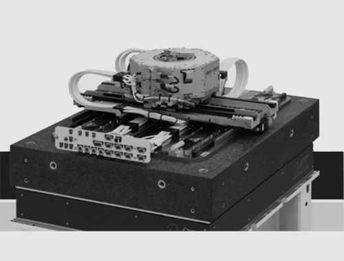
Direct Force Interference: These are vibrations transmitted through mechanical connections (like cables or hoses) or reactionary forces generated by the moving parts inside the equipment itself (like a fast-moving wafer stage). Because we know the characteristics of these vibrations, we can usually design specific ways to suppress them.
It's worth noting that many sources generate multiple types of vibration simultaneously. For example, a vacuum pump sitting next to a lab bench sends vibrations through the floor and generates acoustic noise in the air. However, because mechanical vibration transfers energy much more efficiently than sound, ground vibrations and direct forces are usually the biggest troublemakers. Placing that vacuum pump on a shock-absorbing pad can drastically reduce its impact, making its interference negligible compared to other sources.
(2) By Signal Characteristics: Recognizing the "Rhythm"
Periodic Vibration: Typically originating from rotating machinery. The signal has a constant frequency and appears as discrete spikes on a spectrum (often with harmonics). For instance, a fan spinning at a constant speed creates a continuous shake at a single frequency, which can be analyzed using an amplitude spectrum.
Random Vibration: Generated by unpredictable sources like passing traffic or people walking. The signal has no fixed pattern and shows up as continuous broadband noise on a spectrum. To accurately measure this without the data being skewed by the measurement bandwidth, engineers use "Amplitude Spectral Density" (ASD).

(3) By Frequency Range: Finding the Equipment's "Sensitive Zone"
Vibrations act differently depending on their frequency, and they sabotage equipment in distinctly different ways:
Low-Frequency Vibration (Typically <10Hz): Long wavelengths, high energy. Mostly comes from building structures and distant traffic, traveling through foundations and floors. It decays slowly and travels far. This type of vibration causes the entire equipment to slowly translate or tilt. For machines like interferometers or lithography scanners, this is like the very ground beneath them shifting, instantly destroying overlay and alignment accuracy. Passive isolation systems (like air-bearing tables) often have a natural frequency of 1-3Hz, meaning they might accidentally amplify vibrations in this range. Therefore, active vibration isolation is the go-to solution for low frequencies.
Mid-Frequency Vibration (Typically 10Hz-100Hz): Mostly comes from small-to-medium machinery (fans, water pumps, compressors, elevators, walking humans). It hits the equipment through both structural conduction and acoustic coupling. The most critical limits in standard VC curves are concentrated right here. This is the most sensitive frequency band for the vast majority of precision equipment. Fortunately, passive isolation technology is highly effective here, boasting isolation efficiencies up to 99%.
High-Frequency Vibration (Typically >100Hz): Short wavelengths, low energy, fast decay. Usually generated by internal motors (like high-speed rotors, turbo-molecular pumps, mechanical pumps). While it won't move the equipment as a whole, it causes the surface to locally "jitter," directly messing with the tip of a scanning probe microscope or the relative position of optical lenses. Here, fighting vibration relies less on isolation and more on the system's internal damping—high damping materials quickly absorb high-frequency energy, preventing continuous ringing.

3. How Vibration Hacks into Precision Equipment
Vibration doesn't just "break" equipment; it couples with the machine through physical pathways to cause functional chaos:
Direct Structural Transmission: The shake travels through the foundation and mounts into the machine body, moving the whole structure and ruining the measurement or machining baseline.
Acoustic-Solid Coupling: Sound waves bash against the equipment's casing or isolator diaphragms, exciting surface vibrations that creep into sensitive internal components.
Reaction Force Excitation: When a moving platform inside the machine (like a wafer stage in semiconductor gear) accelerates or decelerates, its reaction force kicks back against the machine's base, generating internal vibrations.
The ultimate fallout of these mechanisms? Blurred optical imaging, lost positioning accuracy, a drop in the signal-to-noise ratio, and the long-term degradation of the machine's stability. In highly industrialized arenas like semiconductor manufacturing, exceeding vibration limits causes an immediate bloodbath in production yields. For example, during 12-inch wafer lithography, a mere 1μm vibration at 20Hz can blow up a ±2nm linewidth error into a ±10nm error. The yield plummets from 90% to 70%, resulting in hundreds of millions in economic losses every year.
4. Frequencies and Amplitudes of Common Sources
Accurately identifying the "villain" (the source) is the prerequisite for solving a vibration problem. Blindly throwing isolators at a machine won't work and wastes money.
Common vibration sources, their frequencies, and amplitudes:

5. The Benchmark: Vibration Criterion (VC) Curves
We’ve covered the basics—how vibrations behave, travel, and wreak havoc. But in the real world of engineering, simply knowing the concepts isn't enough. We need a scientific, standardized "pass/fail" grading system to guide facility design and equipment installation.
Enter the Vibration Criterion (VC) Curves. Widely adopted in precision engineering, semiconductor manufacturing, and biopharma, these curves are not just a jumble of parameters. They are the universal "health checkup guide" that ensures an environment is safe for high-tech machinery.
(1) The Backstory: From "Guesswork" to "Quantifiable Standards"
Origins: The VC curves were born out of absolute necessity. In the 1970s and 80s, the semiconductor industry was leaping from micrometer to sub-micrometer chip architectures. Machines like lithography scanners became exponentially more sensitive; even a micrometer of drift could ruin a chip. The problem? Total industry chaos. Every manufacturer defined a "good environment" differently. Some used displacement (≤0.5μm), some used acceleration (≤0.1g), and frequency bands were all over the place. This wild west caused massive disputes between equipment builders, facility architects, and end-users. To solve this, vibration control experts, led by Colin Gordon, compiled massive amounts of experimental data to create a unified standard: the VC Curves. Today, it is the undisputed global benchmark.
The Goal: The VC curves act as a universal technical translator.
For manufacturers: They can specify "Requires VC-C environment," making demands crystal clear.
For end-users: They can evaluate an existing room or set targets for a new lab.
For engineers: It provides a concrete target for designing architectural structures and isolation systems.
In short, VC curves turned vibration control from a dark art into a measurable science.


(2) Reading the VC Curves
VC curves are a family of lines plotted on a graph, with Velocity on the Y-axis and Frequency on the X-axis. The grades range from a lenient VC-A down to an incredibly strict VC-G (with VC-M generally considered the lowest measurable limit today).
X-axis (Frequency in Hz): Covers the critical 1Hz-100Hz danger zone. It uses "one-third octave band" center frequencies (e.g., 1Hz, 1.25Hz, 1.6Hz... 80Hz).
Y-axis (Velocity in mm/s or in/s): Represents the Root Mean Square (RMS) vibration velocity within a specific one-third octave band. The smaller the number, the stricter the requirement.
The Rule: To pass a specific grade (say, VC-C), the measured RMS velocity in every single one-third octave band between 1Hz and 80Hz must stay below the VC-C line (roughly 12.5μm/s). If even one frequency band spikes over the line, the entire room fails the test.
(3) Why Measure in "Velocity"? (And not Displacement or Acceleration?)
In the field, we record raw acceleration data, run it through a Fast Fourier Transform (FFT), and mathematically integrate it into a velocity spectrum. Why this specific workflow?
The Energy Connection: The destructive energy of a vibration is directly proportional to the square of its velocity. It’s a clean, direct relationship. Acceleration and displacement, however, are skewed by frequency. If you only look at acceleration, a low-frequency rumble looks harmless, but it actually carries massive energy that can destroy equipment baselines. Velocity gives us the true story of the energy.
Human and Structural Response: Studies show that human sensitivity to vibration, as well as the response of most buildings, correlates directly with vibration velocity across a broad frequency range.
Balancing High and Low: Displacement exaggerates low frequencies; acceleration exaggerates high frequencies. Velocity is the "Goldilocks" metric, perfectly capturing the danger across the critical 1Hz-80Hz band without bias.
(4) Why Only 1Hz to 100Hz?
Why not measure from 0 to 200Hz? Because decades of data prove that precision equipment is uniquely vulnerable within this specific window:
<10Hz (High Resonance Risk): This is where buildings shake (floor flex, foundation settling). Unfortunately, it’s also the exact natural frequency of most equipment frames. If the building shakes at 5Hz and the machine's frame naturally resonates at 5Hz, the vibration amplifies 10 to 100 times.
10-100Hz (Direct Functional Interference): This is where pumps, HVACs, and motors hum. It’s also the exact frequency where optical lenses blur and lithography stages lose their nanometer tracking.
>100Hz (Easily Handled): High-frequency vibrations lose energy rapidly in the air and through structures. Furthermore, heavy precision equipment naturally filters out high frequencies, and standard isolation tables kill them easily. Therefore, VC curves don't need to overcomplicate the standard by focusing heavily past 100Hz.
(5) Why "One-Third Octave"?
The curves group frequencies into "one-third octave bands" instead of a continuous sweep. This brilliantly balances "testing precision" with "practical engineering," aligning with ISO standards for how vibrations impact buildings and humans.
In the real world, professional engineering makes all the difference. ND GROUP brings decades of field experience to provide end-to-end vibration control:
Environmental Assessment: We measure your lab against VC standards to pinpoint exactly what is shaking and why.
Custom Solutions: If low frequencies are failing the test, we deploy our flagship Active Vibration Isolation Systems (canceling vibrations down to 0.2Hz with 99.9% efficiency at 2Hz). For mid/high frequencies, our high-performance pneumatic passive tables provide a cost-effective shield. We also build hybrid active-passive systems for full-spectrum protection.

Verification: After installation, we test again to prove your equipment now lives in a certified, safe environment.
6. Building the "Vibration Filter": How to Isolate Precision Equipment
We can't stop the world from shaking, but we can build a barrier. The goal of vibration isolation is to insert a "vibration filter" between the shaking ground and the sensitive machine.
(1) Passive Vibration Isolation
Passive isolation acts much like the suspension system in a luxury car. It uses mechanical components to weaken the transfer of movement from the floor to the equipment.
Imagine a semiconductor machine etching a 7-nanometer chip. If the floor moves by just 0.01 mm (1/5th the thickness of a human hair), the chip is ruined. Passive isolators use springs and dampers to reduce that floor movement into "sub-nanometer" levels, creating a virtually motionless environment.

It requires no electricity—just physics. The classic model is the Mass-Spring-Damper system:

Mass (M): The precision equipment you are trying to protect.
Spring (k): The bouncy element (like an air spring) that holds the weight and absorbs the shock.
Damper (b): The energy-absorbing element (like oil or a tiny air valve) that converts the kinetic energy of the shake into heat, stopping the equipment from bouncing endlessly.
(2) Active Vibration Isolation
Passive isolation is great, but it struggles with ultra-low frequencies (<5Hz). Enter the modern marvel: Active Vibration Isolation.
Think of this as noise-canceling headphones for your equipment.
Real-time Monitoring: Ultra-sensitive sensors constantly listen to the floor for incoming vibrations.
Active Cancellation: A high-speed computer calculates the exact counter-force needed.
Actuation: Voice coil or piezoelectric motors instantly fire back, pushing against the machine with an equal and opposite force to completely cancel out the incoming shake.
By combining heavy-duty passive springs with high-tech active motors and sensors, closed-loop active systems can effortlessly erase vibrations from 0.5Hz all the way up to hundreds of Hertz.
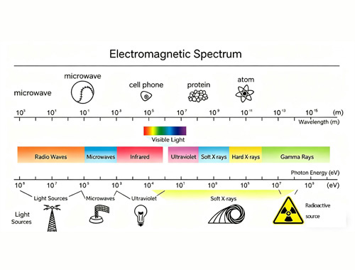
Part II: Active Magnetic Field Cancellation Systems
As our technology grows more sensitive, it's not just physical shaking we have to worry about. Magnetic fields are another invisible ghost haunting high-tech labs. To combat this, Active Magnetic Field Cancellation Systems have become an indispensable tool, offering vastly higher efficiency and precision than old-school shielding methods.

How It Works (The Core Principle)
Instead of just building a thick metal box to block magnetism, an active system fights fire with fire. It uses advanced electronics to deliberately generate a counter-magnetic field that perfectly cancels out the interfering magnetic field in the room.
The Workflow:
Detect: Highly sensitive magnetic sensors (like Fluxgates or Hall-effect sensors) map the ambient magnetic field in the room.
Calculate: A smart control unit analyzes the interference and calculates the exact intensity, frequency, and direction needed for a counter-field.
Cancel: Electromagnetic coils surrounding the equipment are instantly energized, generating a reverse magnetic field that neutralizes the ambient interference.
Adapt: The system operates in a continuous feedback loop, adjusting in real-time to keep the environment perfectly "magnetically quiet."
Why Do We Need It?
Magnetic interference is everywhere:
DC Fields (Static): Constant fields, like the Earth's magnetic field or large steel structures in a building.
AC Fields (Alternating): Fluctuating fields from the power grid (50Hz/60Hz).
Random Fields: Surges caused by a passing subway train, heavy traffic, or an elevator moving nearby.
Equipment Interference: Magnetic spikes caused when large lab equipment turns on or off.
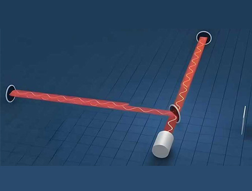
For tools like Scanning Electron Microscopes (SEM) or electron beam lithography, a stray magnetic field acts like a strong wind blowing a stream of water—it bends the electron beam, causing images to blur, drift, or tear entirely.
By mastering the electromagnetism, an Active Magnetic Field Cancellation System essentially creates an invisible forcefield, ensuring that even in the middle of a bustling city, the world's most delicate instruments can see down to the atom with absolute clarity.