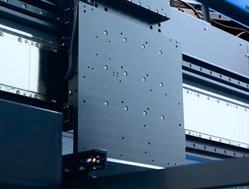
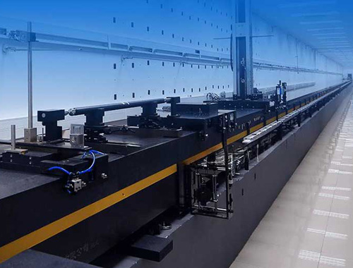
Application Background of Gantry
In fields like wafer inspection, laser micromachining, 3D measurement, and digital printing, the requirements for planar motion are quite high: think large span, heavy load, smooth movement, and low inter-axis coupling. That’s why motion control here usually needs to be fast-responding, quick to tune, low in error, and high in precision.
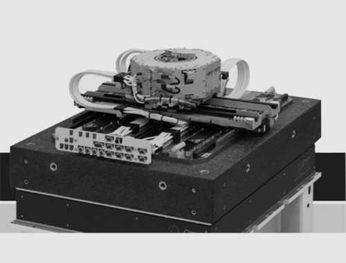
In these scenarios, the traditional cross-shaped XY platform can barely meet the demands — which is where the gantry structure comes in. As shown in the figure below, a gantry consists of two motors and a mechanical structure, with the X1 axis and X2 axis working together to achieve movement along the X-axis direction.

Gantry Structure Diagram
Common Gantry Control Methods
01 Single Feedback - Single Motor
Only one side is powered by a motor, while the other side is supported by guide rails and moves through mechanical stress.
Advantage: Relatively cost-effective.
Disadvantage: Poor control performance, which can easily cause damage to the machinery.

Gantry Structure - Single Feedback - Single Motor
02 Single Feedback - Multi-Motor
It’s equivalent to connecting two motors in parallel, with one set of signals controlling both motors simultaneously.
Advantage: Thrust can be coupled to the center of the gantry axis, reducing the impact of weak mechanical rigidity.
Disadvantage: It has extremely high requirements for mechanical installation and motor consistency; any deviation can easily lead to poor control performance. The feedback center is not collinear with the gantry axis center, resulting in insufficient control performance and limiting the final control precision level.

Gantry Structure - Single Feedback - Multi-Motor
03 Master-Slave Control
A controller coordinates the synchronous movement of two drivers.
Advantage: Works well in low-speed scenarios and offers high cost performance in engineering implementation.
Disadvantage: Synchronization performance degrades in high-speed motion scenarios, with significant inter-axis coupling effects, making it unsuitable for high-dynamic gantry control.

Figure: Gantry Structure - Master-Slave Control
04 Cross Decoupling Algorithm
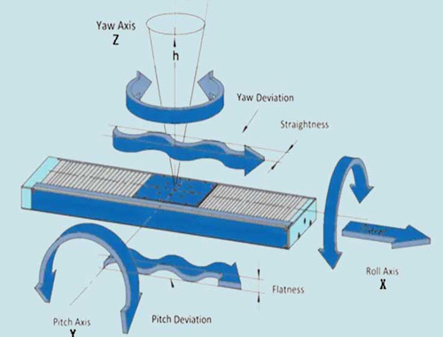
Cross decoupling control of the gantry is performed at the driver level, enabling automatic control of the gantry’s dual-axis motors and coupled feedback. It has independent PID parameters for the control rigidity of the gantry axis. It can even perform dynamic control of the yaw angle.
Advantage: Can greatly improve control performance and solve the problem of gantry mechanical coupling. It is simple to develop and operate at the controller level.
Disadvantage: Requires a large amount of computation and has high requirements for controllers and drivers.

Gantry Structure - Cross Decoupling
The gantry algorithm is a type of cross decoupling algorithm
It treats the gantry as a Multiple-Input Multiple-Output (MIMO) system, controlling it through two objects — the forward direction axis and the yaw axis — rather than two motors. This allows for independent control of the two coupled axes and reduces the impact of mechanical coupling.

Gantry Mode - Cross Decoupling
System Setup and Debugging
Wiring
Select the corresponding axes for the gantry, connect the motors and encoder wires. Ensure that the counting directions of the two encoders are consistent.

Figure: Gantry Debugging Mind Map
Debugging
After enabling the gantry algorithm, debugging the gantry is roughly the same as debugging a single axis. The only difference is that AXIS1 represents the gantry vertical direction (GANTRY AXIS) — even though two motors are moving, the system treats it as one axis — and AXIS2 represents the YAW AXIS (yaw axis). (Yaw is also achieved through the movement of two motors, but the system treats it as one axis.)
Figure: Comparison Between Non-Gantry Mode and Gantry Mode
Current Setting
The GANTRY AXIS is responsible for outputting force to drive the load, so it needs to be set with a larger current; the YAW AXIS is responsible for adjusting the attitude, so only a smaller current is needed.
Position Feedback
The axis position feedback in gantry mode is not the same as the actual motor position. Due to mechanical manufacturing deviations, the gantry may not be completely perpendicular to the guide rails. A FPOS(axis1) = 0 is not necessarily the optimal position; on the contrary, a certain tilt is actually beneficial for reducing friction. Therefore, it is necessary to measure the optimal tilt angle during gantry debugging.
Motor Enable
The gantry requires the joint movement of two motors to operate. When only one axis is enabled, both motors will actually be enabled; when one axis is disabled, both motors will be disabled.
Heavy Load on the Beam Axis
It is necessary to perform multiple sets of dynamic parameter analyses when the load is at different positions to ensure that the system maintains high motion performance in all situations.
Related Applications Combined with Gantry
01 Gantry Mode PEG
The Position Event Generator (PEG) can trigger pulses (PEG Pulses) at precise feedback positions, which can be used to trigger external devices such as cameras and lasers.
It generates PEG Pulses at the bottom layer of the driver hardware by comparing the actual encoder position with a set of predefined values. Since the calculated positions of the two axes in gantry mode are different from the positions fed back by the motors, conversion is also required when using the PEG function to trigger the PEG signal correctly.
02 Gantry Mode Dynamic Compensation
Both axes of the gantry can be compensated. Compensation for the gantry axis is used to improve precision. Compensation for the yaw axis can reduce friction and current overcharge in rigid gantries, improving dynamic performance. In flexible gantries, it is used to improve precision while enhancing the YAW mechanical indicators of the gantry axis.