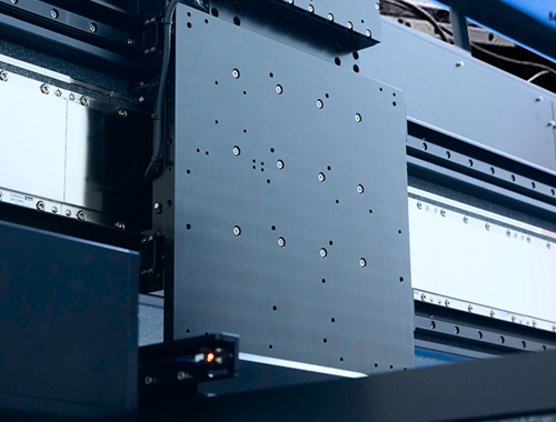
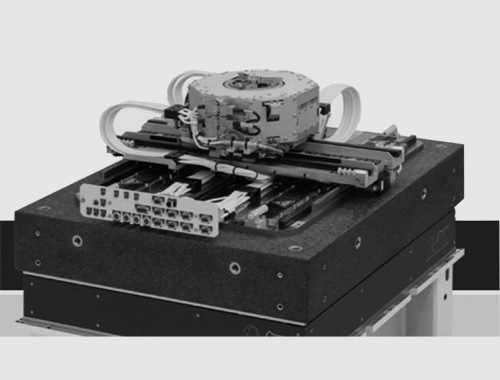
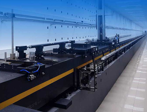
In simple terms, a gantry structure is essentially a giant, high-tech door frame: a solid crossbeam connects two supporting legs that are securely anchored to the ground. It is an absolute staple in motion control platforms. Why is it so popular? Because this overhead architecture allows end-effectors—such as pick-and-place tools, inspection cameras, or laser heads—mounted on the upper axis to effortlessly approach the workpiece from above.
Generally speaking, gantry systems come in a few distinct evolutionary stages: Single-Drive Single-Feedback, Dual-Drive Single-Feedback, Dual-Drive Dual-Feedback, and the rarely utilized Single-Drive Dual-Feedback.

Comparing Different Architectures
Single-Drive Single-Feedback (SDSF):

[ Image: Single-Drive Single-Feedback]
Let's start with the baseline. The SDSF architecture utilizes exactly what the name implies: a single motor to drive the system and a single encoder scale to provide position feedback. It’s budget-friendly, technically straightforward, and perfect for applications where cost-effectiveness trumps extreme precision.
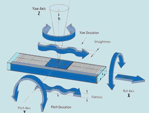
However, physics presents a challenge. Because the driving force from the single motor is applied far from the system's "center of yaw" (the pivot point of structural twisting), it naturally triggers the crossbeam's yaw resonance modes. Furthermore, because the single sensor is also positioned far from this center, the system can neither distribute forces optimally nor accurately measure the actual yaw displacement. This double handicap severely limits the system's control bandwidth and throttles its dynamic performance.
To support this setup, engineers typically rely on linear guide rails and runner blocks. Unfortunately, the inherent mechanical friction in these guides prevents the system from achieving top-tier repeatability.

[Image: Frequency Response Function of SDSF]
| Q: How can we boost the performance of an SDSF gantry? A: Beef up the stiffness and trim the fat! |
The severity of the crossbeam's yaw mode depends entirely on its stiffness-to-mass ratio. By applying the "stiffer and lighter" engineering principle, this ratio shoots up, thereby improving dynamic performance. With higher rigidity, structural deformations caused by guide rail friction decrease, which in turn enhances repeatability. However, due to the inherent physical limitations of this single-drive architecture, these improvements can only take you so far.
Dual-Drive Single-Feedback (DDSF):

[Image: Dual-Drive Single-Feedback]
Stepping up the game, we have the DDSF architecture. Compared to its simpler cousin, this setup adds a second motor to the opposite side of the crossbeam. In a perfect, theoretical world, the combined and synchronized force of two motors would completely suppress those pesky yaw modes.
But the real world is messy. The crossbeam usually carries a moving payload (the end-effector moving side to side), meaning the system's center of gravity (CoG) and vibration mode shapes are constantly shifting during operation. If the motors keep pushing with a fixed force ratio while the CoG changes, the yaw mode will inevitably be triggered, albeit slightly. If the single feedback encoder scale is mounted far from this shifting CoG, the vibration components it picks up become significant, dragging down the overall dynamic performance.
| Q: How do we optimize a DDSF gantry? A: Maximize stiffness, minimize mass, and position the encoder scale as close to the yaw center as physically possible. |
Dual-Drive Dual-Feedback (DDDF):

[Image: Dual-Drive Dual-Feedback]
Now we enter the big leagues. The DDDF architecture is the gold standard for high-performance gantries. It features two motors and, crucially, a second feedback encoder scale on the opposite side.
This dual-feedback setup is a game-changer because it allows the control algorithms to perform engineering magic. Instead of clumsily commanding two single motors independently, the algorithm mathematically decouples the system into two virtual axes: the gantry axis (moving forward/backward) and the yaw axis (twisting).
It takes the average (or a carefully calculated weighted value) of the two encoder scales as the precise feedback for the gantry axis, and uses the angular difference between them as the feedback for the yaw axis. The controller then governs these two virtual axes independently. In practice, this clever math acts exactly as if a sensor were placed dead-center in the yaw pivot point. The modal vibration components drop to virtually zero, unlocking a massive surge in dynamic performance.

[Image: Frequency Response Function of Gantry Axis]

[Image: Frequency Response Function of Yaw Axis]
Crucial Considerations in Rigid Coupling Design
01 The Constraint Conundrum: Rigidly Fixing Both Ends
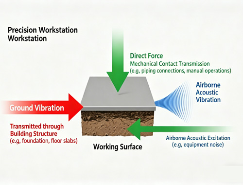
When the crossbeam is rigidly bolted down and its length is completely constrained, nature fights back through thermal expansion. As ambient temperatures fluctuate, or as the rapidly moving axes generate heat that transfers into the beam, the metal expands and contracts. As the crossbeam attempts to change its length (a phenomenon that gets significantly worse on wider gantries), the friction on the lateral axes spikes, inevitably causing the beam to bow outward or twist.
02 The Mechanical Alignment of Linear Guides
Installation Precision: It is physically impossible to install linear guide rails flawlessly. If the two parallel rails have even microscopic alignment errors, they will experience uneven friction along their travel path. This wreaks havoc on servo performance and forces the motors to output significantly more driving force than theoretically calculated.
The Scaling Problem: These installation errors amplify dramatically as the gantry gets larger. Consequently, building a massive gantry structure to meet ultra-high precision requirements using a strictly rigid baseline is astronomically expensive—and sometimes impossible.
| The Solution: Most rigidly mounted bearings are designed with a tiny bit of inherent "give" or compliance, allowing for microscopic deviations in specific directions. Ultimately, however,performance remains tethered to machining precision, bearing clearances,and the sheer size of the gantry. |
03 The "Tug-of-War" in Dual-Encoder Rigid Coupling
Using two encoders is fantastic because it feeds the actual yaw error (the physical difference between the two motors) directly to the controller. However, just like linear guides, the encoder tapes have installation tolerances and intrinsic manufacturing errors. These errors act just like mechanical bearing misalignments.
At this point, the controller desperately tries to drive both motors to their exact commanded micro-positions. If the encoder scale errors clash with the rigidly constrained crossbeam, the controller will pump massive amounts of electrical current into the motors to force them into alignment—so much so that it can physically stretch, bend, or warp the heavy metal beam. The two motors end up "fighting" each other, leading to system instability, excessive heat, and dangerously high continuous motor effort.
The Solution: To stop the mechanical fight, engineers configure the controller to apply an error compensation table, forcing one controller to artificially match the other encoder's readings. Under these conditions, the crossbeam is allowed to naturally "relax" (the motors stop fighting). However, this is a mathematical compromise; it doesn't mean the true physical yaw error is zero. In fact, achieving absolute zero yaw error on a rigid gantry is a pipe dream unless every aspect of the mechanical installation (parallelism, straightness,flatness) is absolutely flawless.
04 Flexible Coupling: The Software Solution
An alternative approach is a flexible coupling design. This mechanical setup allows one side of the crossbeam a certain degree of freedom in the yaw direction, while permitting the other side to translate and pivot freely. Because it's mechanically loose, flexible coupling strictly requires two completely independent drives. While these sophisticated control components carry a heftier price tag, this elegant approach leverages advanced software algorithms to completely compensate for physical mechanical shortcomings.
How to Choose the Right Gantry Architecture? Selecting the perfect gantry architecture is a balancing act between performance targets, manufacturing budgets, and engineering complexity. When your primary goal is keeping costs low while maintaining moderate performance (think consumer-grade 3D printers or basic packaging machines), the Single-Drive Single-Feedback architecture is your reliable workhorse. However, if you are chasing uncompromising high performance—such as the sub-micron precision required in semiconductor manufacturing equipment—you must step up to the Dual-Drive Single-Feedback or, ideally, the formidable Dual-Drive Dual-Feedback architecture. |