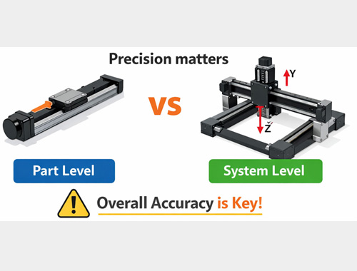
System positioning accuracy refers to a positioning system's ability to precisely reach its target destination within a machine and stably hold that position. Simply put, it is the actual physical deviation between where the equipment ends up and where you told it to go.
It represents the true capability of the fully assembled machine. In engineering, we constantly emphasize that the accuracy of a single module and the accuracy of the entire system are two completely different concepts. A single module’s accuracy specification only tells you about the errors of that isolated part. The system's accuracy, however, is the ruthless accumulation of every single component’s microscopic errors stacked together!
Defining the Core Metrics:
Positioning Accuracy: The precision with which a system successfully reaches its exact target destination at any given moment.
Repeatability (Repetitive Positioning Accuracy): The consistency of the system—how tightly it can return to that exact same location over multiple separate attempts.
The Clash: System Accuracy vs. Single Component Accuracy
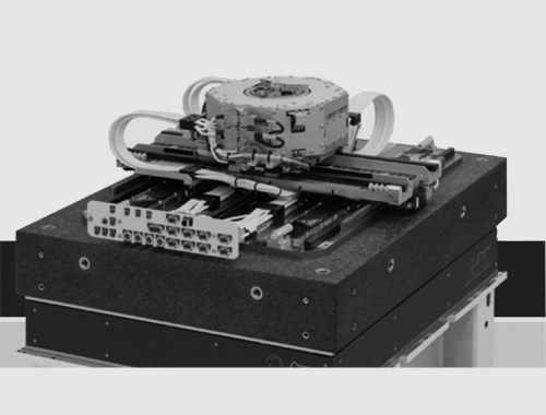
When we talk about System Positioning Accuracy, we are looking at the integrated performance of the entire platform—such as an XYZ motion stage or a massive gantry system. This includes the mechanical hardware, sensors, drives, and control systems. System accuracy is a holistic result. It forces you to look beyond how good one component is and consider mechanical mating, error accumulation, control algorithms, and even environmental impacts.
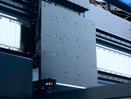
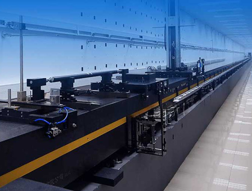
Let’s look at a gantry system as an example. It is typically built from multiple linear modules, transmission systems, and heavy supporting structures. If just one platform has a slight mechanical error, that error doesn't stay isolated; it ripples through the guideways and connecting joints, infecting the rest of the machine.
Microscopic misalignments between multiple systems can cause mechanical coupling issues, degrading the coordination of the entire setup. Throw in high-speed motion, and any lack of structural rigidity will immediately trigger vibrations, leading directly to positioning errors.
Imagine a dual-drive gantry system. If one axis boasts a positioning accuracy of ±2μm, but the parallel axis has an error of ±5μm, the entire gantry platform will skew. In this scenario, you simply cannot rely on the hardware alone—you must implement active synchronization and sophisticated error compensation algorithms to rescue the overall system accuracy.


On the other hand, Single Component Accuracy (like the spec of a standalone X-axis module) merely tells you how well that one piece of metal moves on a test bench. It might have a stellar rating. But once installed, if the tolerance stack-up between multiple components isn't strictly controlled, or if structural vibrations and thermal expansion are left uncompensated, the final assembly will suffer. Influenced by material swelling, poor mechanical rigidity, and weak motion compensation algorithms, your expensive system platform might actually perform worse than its cheapest individual component.
This is why holistic, system-level design and error compensation are absolutely vital.

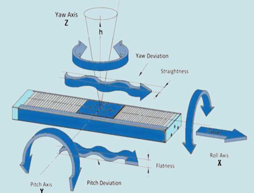
The Invisible Culprit: Abbe Error
When diagnosing what kills a single system's positioning accuracy, one critical but easily overlooked factor is the Abbe Error.
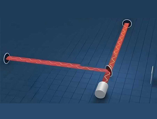
Abbe error occurs when there is a physical offset (distance) between the measurement sensor (like an encoder) and the actual point of interest being moved, and the system experiences a tiny angular tilt during motion.
It is defined by a simple but unforgiving formula:E=L⋅Δθ
The golden rule here is: The greater the offset distance, the larger the amplified error.

Let's break down how Abbe error sabotages your precision in the real world:
The "Lever Arm" Effect: The longer your mounting arm, the more violently an angular tilt is amplified. Suppose the mounting arm experiences a tiny tilt of just 40 arcseconds. Over a travel stroke of 250mm, the tip of that arm will actually swing to 250.100mm. That invisible angular tilt just generated a massive 0.1mm linear error on the X-axis.
The "Bowed Guideway" Effect: If the mechanical guideway isn't perfectly straight and bends in a slight arc, it will introduce an unwanted lateral shift—for example, a +25μm offset on the Y-axis. Even if the angular error happens to be localized exactly at the 250mm mark—potentially mitigating that specific lateral deviation—the original longitudinal (X-axis) error stubbornly remains.
The Solution: Abbe error is completely invisible to the naked eye. The smartest approach for engineers is to simply assume that angular errors always exist in the system. The defense is proactive structural optimization—designing the layout to minimize the offset distance and its impact. When you actually need to measure and map these angular errors, you must bring in high-end metrology equipment, such as a laser interferometer or an autocollimator.