Imagine a motion device—like a precision positioning stage in a large scientific facility—as a train that needs to travel along a perfect, invisible track. Its primary job is to create exactly the movement you want, along an ideal trajectory. More importantly, it has to hit its target destination reliably and reproducibly, time and time again.
However, the real world is messy. Sneaky culprits like friction between moving parts, the sheer weight of the guide rails, or the mechanical bending caused by a heavy payload can easily bump the device off its perfect path. Suddenly, where the device actually ends up is slightly different from where it was supposed to go. In this section, we are going to dive deep into the fascinating world of motion control. We'll explore the hidden forces that mess with these devices and learn exactly how engineers characterize their precision and accuracy.
Positioning Basics
Think of any positioning stage as existing in a 3D space with six ways to move—what engineers call "six degrees of freedom." It can slide along three straight lines (the x, y, and z axes) and rotate around those same three axes. The whole point of a stage is to lock down the movement to a perfect, intended path by restricting it to specific degrees of freedom. Any rogue movement in an unconstrained direction means the stage is drifting off course.
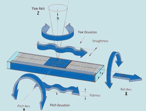
Let's take a linear translation stage, for example. Its sole purpose is to restrict movement to a perfect straight line. When it wanders off, we call this off-axis linear error runout. Runout measures exactly how much the stage drifts from its intended straight-line trajectory. It is broken down into two components at right angles to each other: flatness and straightness.
Take a look at Figure 1, where an ideal linear movement is constrained to the x-axis. In this scenario, a bump up or down along the z-axis is a flatness deviation, while a wiggle left or right along the y-axis is a straightness deviation.
But a stage doesn't just slide off course; sometimes it tilts. This angular deviation—where the actual working point (the spot doing the measuring or cutting) twists—is known as angular deviation or tilt. Just like an airplane, this tilt has three orthogonal components: pitch, roll, and yaw (see Figure 1), and a stage can suffer from a complex combination of all three. To make things even more interesting, when you stack multiple stages together to build a multi-axis system, cross-coupling can occur. This means moving one axis accidentally triggers an unwanted twitch in another.

Figure 1. Runout errors in a linear stage, showing flatness and straightness (top left). Angular deviations—roll, pitch, and yaw—in a linear stage (bottom left). Off-axis deviations in a rotary stage (right).
Now, what about stages that spin rather than slide? For rotary stages, we have to watch out for eccentricity. Imagine a spinning top whose center shifts slightly as it turns; eccentricity is the radial deviation (perpendicular to the axis of rotation) of the center of rotation from its average position over one full turn (see Figure 1). You might also hear it called radial runout. A stage with flawless, perfectly centered bearings would have zero eccentricity.
Then there's wobble. Wobble happens when the rotation axis tilts away from the perfect, ideal axis during a revolution. You'll usually spot this as a rhythmic, cyclic tilting of the rotating platform surface as it spins. Just like eccentricity, wobble is almost always the fault of imperfect bearings.
Beyond just traveling along the right path, a stage must reliably reach its destination and stay put. Imagine trying to hit a bullseye. If you approach it from one direction versus the opposite direction, the physical gap between your two final positions is called reversal error (see Figure 2).
This error is a tag-team of two mechanical gremlins: backlash and hysteresis.
Backlash happens when interacting mechanical parts inside the drive system move, but don't actually generate any output movement. Think of the slop or gap between gear teeth, or slight mechanical bending. Not every system has backlash, but when it does, it wreaks havoc on bi-directional repeatability (more on that below). The good news? Because backlash is predictable, a smart motion controller can usually compensate for it.
Hysteresis, on the other hand, is the part of the reversal error that depends on the system's "memory" or recent history. It arises from the elastic forces within various components, revealing itself exactly when the forces acting on the system reverse direction. Hysteresis messes with both bi-directional repeatability and accuracy. Unlike backlash, hysteresis haunts every mechanical system, even if its value is microscopically small.
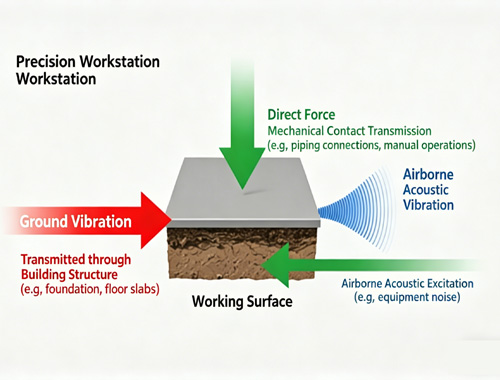
While reversal error is about getting to the target, position stability is about staying there within a designated time frame. It is the sum of drift and vibrations. Drift is a slow, sneaky wander away from a stable position, mainly caused by shifting lubricants and temperature changes. Vibrations are tiny, rapid jitters caused by the environment (like air drafts or cooling fans) or the electronics (like motor drivers).

Figure 2. An illustration of position deviation in a linear stage—simply put, the actual (or measured) position the working point reaches, minus the intended target position.
Beyond just position, the rate of position change—velocity—is a massive deal in motion control. When you look at a spec sheet, the maximum velocity is usually rated under the stage's normal load capacity (more on loads below). If you lighten the load or use a beefier motor driver, you might push it even faster. The minimum speed, however, relies heavily on the system’s velocity stability—its ability to hold a steady pace within specific limits, usually expressed as a percentage of the desired speed. Acceleration is simply the rate of speed change, usually programmed to get the system to its top speed within a set time.
Playing the ultimate spoiler to speed, stability, and acceleration is friction—the resistance between touching surfaces that fights against movement. Friction can come from air drag, sliding contact, depleted lubrication, system wear and tear, or even the viscosity of the lubricant itself. The trickiest kind is stiction (static friction)—the stubborn resistance you must overcome to get a stationary object to move. Because stiction is almost always stronger than dynamic friction, it takes a harder push to start the stage than to keep it going. As a result, when you apply that initial hard push, the object often breaks free with a sudden "jump," causing an irritating overshoot in position or speed.
Every stage has a limit to how much force it can handle without compromising its specs. This is its load capacity. This maximum force includes both static dead weight (mass times gravity) and dynamic forces (mass times acceleration). Crucially, dynamic forces must account for any outside interference, like vibrations. The maximum acceleration a stage can impart to a payload is strictly gated by the accelerating force it can generate without blowing past its load capacity.
Specifically, engineers break this down into different types:
Centered normal load capacity: For a linear stage, this is the maximum weight pushing straight down on the carriage, assuming the center of gravity is perfectly balanced and perpendicular to the axis of motion (see Figure 3). For a rotary stage, it's the maximum load along the axis of rotation.
Transverse (or side) load capacity: This is the maximum force pushing sideways, perpendicular to the axis of motion but along the carriage surface. It is usually significantly lower than the normal load capacity.
Axial load capacity: This is the maximum force pushing straight along the drive train. If you mount a linear stage vertically, its rated vertical load capacity is usually limited by this axial limit.
Keep in mind, if your load is off-center, the stage's maximum load capacity instantly drops.
Finally, we have inertia, which is essentially a payload's stubborn refusal to change its speed. The higher the inertia, the more muscle (force) you need to accelerate or decelerate the load. If your available drive force is limited, you have no choice but to dial down your allowable acceleration and deceleration to manageable levels. For rotary stages, the moment of inertia is calculated as the product of mass elements and the square of their distance from the rotation axis. The maximum inertia listed for a rotary stage is always calculated based on the maximum torque the system can produce.

Figure 3: The different types of load capacities acting on a positioning stage.
Motion Control Specifications
When choosing the perfect positioning equipment for a specific application, engineers constantly evaluate product specifications—most notably, repeatability and accuracy. Repeatability is frequently confused with Accuracy (or absolute accuracy), but as you can see in Figure 4, a system might have phenomenal repeatability but terrible accuracy.
Accuracy simply measures how closely a given displacement matches a recognized standard. For instance, the runout we discussed earlier directly degrades straight-line accuracy. However, accuracy is a fragile metric; it can be heavily warped by your test setup, environmental conditions, and the exact procedures used to measure the displacement. The beauty of modern motion controllers is that they can digitally "erase" many linear errors just by plugging compensation coefficients into the controller. Therefore, the accuracy spec you see for a specific stage is very often its "compensated accuracy."

Figure 4: A visual breakdown of the crucial difference between Accuracy and Repeatability.
Repeatability, on the other hand, is the true test of a system's consistency. It measures the ability to hit the exact same spot time after time. We categorize this as either uni-directional (always approaching the target from the same side) or bi-directional (approaching from any direction).
In many advanced applications, a motion system's repeatability is actually far more critical than its raw accuracy. Why? Because you can use math to calculate and compensate for systematic accuracy errors, but repeatability is the hard, unavoidable physical limit of the machine after all software compensations are exhausted. At its core, repeatability evaluates the system's ability to consistently land on a commanded position across multiple attempts, from the same or different directions (see Figure 5). The ultimate gatekeepers of repeatability are the reversal error and position stability we talked about earlier. In countless industrial sectors, repeatability is the bedrock of product quality. Without stellar repeatability in a manufacturing environment, it is utterly impossible to build a reliable process that ensures products are manufactured uniformly and always meet the same specs.

Figure 5: How it works in practice: The distribution of position errors from multiple measurements ultimately defines a motion control system's repeatability.
Finally, let's clear up a massive misconception in the industry: Resolution versus Minimum Incremental Motion.
Resolution is technically the smallest slice of movement that the system can be commanded to make and/or detect. However, just because a system can be commanded to move by its resolution value doesn't mean it can consistently execute that tiny step.
That's where Minimum Incremental Motion (MIM) comes in. MIM is the smallest physical step that the device can consistently and reliably perform in the real world. This actual physical output is constrained by all the factors we’ve discussed: friction, payload, external forces, system dynamics, controller performance, vibrations, and system inertia.
MIM should never be confused with resolution, which is often just a number—the smallest digit a controller can display or the smallest tick an encoder can count. In reality, the marketed resolution is frequently much smaller than the actual, physical MIM. This is a highly critical distinction that is often misunderstood, which is exactly why engineers sometimes refer to MIM by a much more honest name: "practical resolution."
If you are interested in our products, please contact us.