Preface: This article is sourced from the internet and is intended for exchange and learning purposes only. Copyright belongs to the original creators; please contact for removal if there is any infringement.
Li Haiyue¹, Cheng Ze¹, Zhao Danni¹, Wang Haowei², Li Deyong¹, Zhang Jiabo¹, Song Xiaodong³, Zhao Linna¹
(1. Beijing Satellite Manufacturing Factory Co., Ltd., Beijing 100094; 2. Beijing Institute of Spacecraft System Engineering, Beijing 100094; 3. School of Aerospace Engineering, Beijing Institute of Technology, Beijing 100081)
Abstract:
How do we test a complex, three-dimensional space robotic arm on Earth when gravity ruins everything? To meet the rigorous demands of multi-dimensional, multi-degree-of-freedom (DOF), high-precision trajectory tracking, and high offloading efficiency during ground tests, this paper introduces a brilliant solution. By analyzing mature microgravity simulation methods, we designed a novel hybrid system combining the suspension method and the air flotation method.
First, we dive into the structural design and working principles of this multi-DOF microgravity simulation system. Then, we put it to the test on a real 3D space robotic arm. The results are highly encouraging: the robotic arm deployed smoothly and reliably. The system generated exceptionally low friction, minimal vertical resistance fluctuations, and incredibly small additional resistance in the deployment direction. With a gravity offloading efficiency exceeding 95%, it perfectly meets the requirements for high-precision testing. This research opens new doors for the future development of ground-based microgravity simulators for large space structures.
Keywords: Suspension method; Air flotation method; Multi-degree-of-freedom (Multi-DOF); High offloading efficiency; Microgravity simulation
CLC Number: TH 12 | Document Code: A | Article ID: 1006-754X(2020)04-0508-08
As aerospace technology advances at breakneck speed, deployable space mechanisms are playing an increasingly crucial role in our exploration of the cosmos. High-precision antennas, massive solar arrays, and highly flexible multi-DOF robotic arms are now standard equipment on modern spacecraft [1-5]. Because these structures are vital, simulating how they will unfold and lock into place in the zero-gravity environment of space is a critical step before they ever leave Earth.
However, as these mechanisms become more complex—moving in multiple dimensions with numerous degrees of freedom—the demands placed on ground-based testing equipment have skyrocketed [6-7]. Today’s testing systems must be highly adaptable, incredibly precise, virtually frictionless, and rock-solid in reliability.
To tackle this challenge, we compared the most mature microgravity simulation methods available today and engineered a hybrid solution. By blending the suspension method with the air flotation method, we built a multi-DOF microgravity simulation system tailor-made for testing 3D space robotic arms. Let's explore how it works and how it performed in real-world tests.
1. The Battle of Microgravity Simulation Methods
Historically, engineers have relied on four main ways to simulate zero gravity on Earth: the suspension method [8-12], drop towers, water buoyancy [13], and the air flotation method [14-20].
The suspension method is the most popular. It uses cables, pulleys, and counterweights to "cancel out" gravity. It's simple and flexible, but it has major drawbacks: high friction, lower precision, delayed movements, mechanical shaking, and a hard time handling complex 3D trajectories.
On the other hand, the air flotation method (think of a giant, ultra-smooth air hockey table) has become increasingly popular. It offers ultra-low friction, is cost-effective, and works beautifully. Its fatal flaw? It requires a perfectly flat, highly polished floor and is generally restricted to 2D movement, making it hard to use for complex 3D space tests.
As for the others, drop towers provide true zero gravity but are insanely expensive and only offer a few seconds of test time. Water pools are high-maintenance and impractical for precise electronics.
2. Meet the Multi-DOF Microgravity Simulation System
A 3D space robotic arm is large, highly flexible, and moves in complex ways. To test it, we need a system that marries the flexibility of the suspension method with the frictionless glide of air flotation. We engineered exactly that—a system that is cost-effective, timelessly durable, and highly precise.
The robotic arm we tested consists of two main sections: a Boom (upper arm) and a Forearm. To ensure a perfect test, our system had to meet three strict criteria:
1)It must seamlessly track the arm's complex 3D trajectory.
2)It must be incredibly "invisible" to the arm. Air-bearing friction must be less than 1‰ (one-thousandth) of the arm's weight; vertical resistance fluctuations must not exceed 2% of the weight; and additional drag in the direction of movement must be under 5 Newtons (N).
3)It must neutralize more than 95% of the arm's gravity.
To achieve this, our system is split into two heroic subsystems: the Boom Vertical Suspension Device (which unloads the weight of the main boom) and the Intelligent Follower Air Flotation Vehicle (which carries the forearm, the simulated payload, and its own hover platform). Together, they handle a total load of 1627N. The suspension device takes 402N (24.7% of the load), while the smart hover vehicle carries the heavy lifting of 1225N (75.3%).
Here is the choreography of the test (illustrated in Fig. 1):
1)The boom connects to a simulated spacecraft interface. The motor drives the boom horizontally to a specific angle and stops.
2)The boom then pivots vertically around its base until it aligns horizontally with the forearm.
3)Finally, the forearm sweeps out horizontally until it is parallel with the boom.
During this intricate dance, our suspension crane and smart hover vehicle must move in perfect harmony with the arm. When the boom pivots vertically, the smart vehicle glides across the floor horizontally while its air-bearing platform rises or falls vertically to match the arm. Sensors constantly monitor force and position, feeding data back to a central brain to make micro-adjustments in real-time.

Fig. 1 Schematic diagram of microgravity simulation deployment test of three-dimensional space unfolding robotic arm
2.1 The Boom Vertical Suspension Device
2.1.1 Structure
Think of this device as a highly responsive, low-friction crane. As shown in Fig. 2, it consists of a rocker arm and a suspension unit (made up of a slider cart, force sensors, pulleys, and timing belts).
The rocker arm shares the same rotational axis as the boom's base joint, moving naturally with it. Fine-tuning knobs allow engineers to keep everything perfectly level. The suspension belts wrap around the boom, connected to freely rotating pulleys that ensure the boom can twist and turn without snapping or dragging. Crucially, force sensors sit between the pulleys and the slider cart, constantly monitoring the offloaded weight to ensure the simulation remains accurate.

Fig. 2 Structure composition of boom vertical suspension device
Because it uses no heavy counterweights, this device is remarkably light (only about 22 kg) and moves on smooth bearings. This minimal mass guarantees it tracks the arm instantly without dragging it back.
2.1.2 Functions
This device is designed to:
1)Offload the boom's gravity.
2)Allow manual tuning of output force for extreme precision.
3)Record real-time gravity-offloading data to review after the test.
4)Connect and disconnect from the robotic arm rapidly.
2.1.3 How It Works
When connected, engineers turn a micro-adjustment knob until the force sensors read the exact required weight. Based on the physics shown in Fig. 3, the offloading forces at the two suspension points are calculated as:
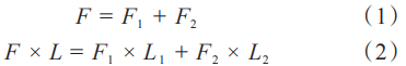
(Where F is the boom's gravity;F₁ and F₂ are the offloading forces; and L, L₁ ,L₂ are their respective moment arms).

Fig. 3 Schematic diagram of force on the boom
2.2 The Intelligent Follower Air Flotation Vehicle
2.2.1 Structure
This is where the magic happens. As shown in Fig. 4 and Table 1, this AGV (Automated Guided Vehicle) consists of a base platform, drive components, an air-floating platform, an air-floating bracket, a gravity balance system, and a smart control system.

Fig. 4 Structure composition of intelligent follow air floatation vehicle

Table 1 Composition of each structure of intelligent follow air floatation vehicle
By utilizing two sets of air-bearing systems (the platform and the bracket), the vehicle operates with near-zero friction. This dual-support system allows the vehicle to follow the robotic arm with incredible sensitivity, maintaining the illusion of true weightlessness.
2.2.2 Functions
This smart vehicle is tasked to:
Offload the gravity of the forearm, payload, and the air platform itself.
Actively follow the payload in full 3D space during the test.
Provide multiple fail-safes to protect the multi-million-dollar space hardware if anything goes wrong.
2.2.3 How It Works
The vehicle works through a delicate balance of gravity offloading and active motion tracking.
1) Gravity Offloading:
The system uses a clever counterweight setup. When the arm swings horizontally, the weights remain in static equilibrium. But when the arm moves vertically, the system transitions to dynamic equilibrium.
If the arm moves upward, the friction acts in the same direction as gravity. The system slightly reduces the counterweight and applies a tiny initial speed, creating a new balance defined by:
Ff+Fₘ=Fp (3)
(Where Ff is friction, Fₘ is counterweight gravity, and Fp is the total weight of the forearm, payload, and platform).
If the arm moves downward, friction opposes gravity. The system slightly increases the counterweight, balancing out as:
Ff+Fp =Fₘ (4)
To prevent disaster—like a snapped cable sending the robotic arm crashing down—we implemented a redundant double-rope system. If one high-strength rope snaps, the secondary rope instantly catches the load.
2) Motion Tracking:
Because the arm moves in sweeping arcs and straight lines, the vehicle must track it perfectly in the X and Y directions. We achieved this by stacking two Position Sensitive Detectors (PSD) vertically. The emitter sits on the bracket, and the receiver is on the platform (see Fig. 5 and 6).

Fig. 5 Structure diagram of PSD

Fig. 6 Layout of PSD
The PSDs measure the exact location of a light beam using four electrodes (L₁、L₂、L₃、L₄ ). The coordinates x, y are calculated as:
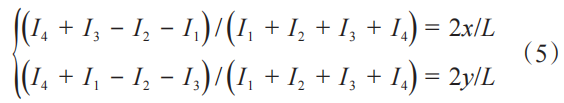
By tracking the shift between two points Δxand Δy, over a fraction of a second Δt, the vehicle calculates its required speed vx,vy:
Any vertical tracking error (σsz) is tied to the horizontal error (σsp) based on the boom's rotation angle (α), calculated as:

Finally, we must account for "side-slip force" (Fig. 7)—the drag created if the air platform tilts even slightly.

(Where Fch is side-slip force, Gcp is the weight of the arm/payload, Gtp is the weight of the bracket, and β is the tilt angle).
Therefore, the total additional resistance in the deployment direction (Fzl) is the friction of the air feet plus the side-slip:


Fig. 7 Schematic diagram of side slip force of air floating platform
3. Putting the System to the Test
While suspension cranes are tried-and-true, our Intelligent Air Flotation Vehicle is a cutting-edge prototype. To prove it works, we ran rigorous functional tests before letting it touch the real spacecraft hardware.
3.1 Functional Testing
1) Following Speed Test:
The space robotic arm deploys slowly, at a maximum speed of 0.04 r/min. To be safe, our smart vehicle needed to track it at twice that speed (>0.08 r/min). As shown in Table 2, the vehicle successfully kept pace even up to 0.09 r/min.

Table 2 Following situation of intelligent follow air floatation vehicle under different deployment speeds
2) Air Flotation Friction Resistance Test:
We loaded the vehicle with a massive 122.5kg simulated payload. To remain "invisible," the friction had to stay below 1.22N (1‰ of the weight). As shown in Table 3, the maximum recorded friction across three tests was a mere 0.92N. Passed with flying colors.

Table 3 Test results of air flotation friction resistance of intelligent follow air floatation vehicle (Unit: N)
3) Vertical Resistance Fluctuation Test:
As the arm moves up and down, resistance cannot spike violently. The limit was set at 24.5N (2% of the load). By adjusting counterweights every 200mm, we mapped the resistance. As Table 4 shows, the maximum fluctuation was only 9.2N. Another pass.

Table 4 Test results of vertical resistance fluctuation of intelligent follow air floatation vehicle
(Note: + means adding weights, - means removing weights.)
4) Deployment Direction Additional Resistance Test:
We tested the total drag across three different robotic arm maneuvers. The goal was to stay under 5N. As Table 5 reveals, the drag peaked at 4.74N. Success.

Table 5 Test results of additional resistance in the deployment direction of intelligent follow air floatation vehicle (Unit: N)
3.2 The Grand Finale: Full Microgravity Simulation
With the system fully vetted, we hooked up a real 3D space robotic arm (weighing 40.2kg) for the ultimate trial, shown in Fig. 8. Over the course of two complete deployments, the arm moved through its complex intersecting planes from a packed state to a fully extended, locked position.
During the whole process, the force sensors (Table 6) showed incredible stability. The total offloaded weight only varied by about 13N across the entire test, effectively carrying between 39.2kg and 40.8kg of the arm. This translates to an error margin of just 1.47% to 2.59%. This proves our hybrid system comfortably achieved an offloading efficiency of greater than 95%, essentially "erasing" Earth's gravity for the robotic arm.

Fig. 8 Microgravity simulation deployment test site of a three-dimensional space unfolding robotic arm

Table 6 Microgravity simulation deployment test results of three-dimensional space unfolding robotic arm (Unit: kg)
4. Conclusion
Massive deployable mechanisms are the backbone of modern space exploration—from solar arrays powering space stations to satellite radars mapping the stars. By perfecting ground-based microgravity simulation tests, we guarantee these systems will perform flawlessly in the harsh environment of space.
Our novel multi-DOF system, combining the suspension method and a smart air-flotation vehicle, proved to be a resounding success. It flawlessly tracked a complex 3D trajectory while keeping friction incredibly low (<1‰ of the arm's weight), maintaining stable vertical movement, and achieving over 95% gravity offloading efficiency. This research provides a powerful, highly reliable blueprint for testing the next generation of multi-DOF deployable space structures, ensuring that humanity's reach into the cosmos remains steady and sure.
References:
[1]MIYASAKA A,HOMMAT M,TSUJIGATA A.Design and ground verification of large deployable reflector[C]// 42nd AIAA/ASME/AHS/ASC Structures,Structural Dynamics and Materials Conference and Exhibit,Seattle, Apr. 16-19,2001. doi:10.2514/6.2001-1480
[2]MEGURO A,HARADA S,WATANABE M. Key technologies for high-accuracy large mesh antenna reflectors[J]. Acta Astronautica,2003,53(11):899-908. doi:10.1016/s0094-5765(02)00211-3
[3] CONG Qiang. The advance of spacecraft engineering [J]. Spacecraft Environment Engineering, 2012, 29(4): 384-387. doi: 10.3969/j.issn.1673-1379.2012.04.006
[4] XIE Zong-wu, GONG Yi-cheng, SHI Shi-cai, et al. A survey of the space solar array technique [J]. Journal of Astronautics, 2014, 35(5): 491-498. doi: 10.3873/j.issn:1000-1328.2014.05.001
[5] NECHYBA M C, XU Y S. Human-robot cooperation in space: SM2 for new space station structure [J]. IEEE Robotics & Automation Magazine, 1995, 2(24): 4-11. doi: 10.1109/100.476624
[6] DUBOWSKY S, PAPADOPOULOS E. The kinematics and control of free-flying and free-floating space robotic system [J]. IEEE Transactions on Robotics and Automation, 1993, 9(5): 531-543.
[7] WHITE G C, XU Y S. Active vertical-direction gravity compensation system [J]. IEEE Transactions on Instrumentation and Measurement, 1994, 43(6): 786-792. doi: 10.1109/19.368066
[8] XU Wen-fu, LIANG Bin, LI Cheng, et al. A review on simulated micro-gravity experiment systems of space robot [J]. Robot, 2009, 31(1): 88-96. doi: 10.3321/j.issn:1002-0446.2009.01.015
[9] GAO Feng, YI Wang-min, GUO Tao. A micro-gravity suspension test facility for space manipulators [J]. Spacecraft Environment Engineering, 2014, 31(1): 52-56. doi: 10.3969/j.issn.1673-1379.2014.01.010
[10] WEI Juan-fang. The equipment for satellite's antenna deployment process zero gravity environment simulation [J]. Space Electronic Technology, 2006(2): 29-32, 42.
[11] GAO Hai-bo, HAO Feng, DENG Zong-quan, et al. Zero-g simulation of space manipulator in furled status [J]. Robot, 2011, 33(1): 9-15. doi: 10.3724/SP.J.1218.2011.00009
[12] DING Min. Design and analysis of large span and scalable test device for zero-g simulation [D]. Harbin: Harbin Institute of Technology, 2015: 7-28.
[13] YAO Yan-sheng. Research on 3-D gravity compensation and equipment of space floating objective simulation [D]. Hefei: University of Science and Technology of China, 2006: 20-24.
[14] YAO Yan-sheng, MEI Tao. Simulation method of space operation on ground-buoyancy method [J]. Journal of Mechanical Engineering, 2008, 44(3): 182-188. doi: 10.3321/j.issn:0577-6686.2008.03.030
[15] CHEN San-feng, MEI Tao, ZHANG Tao, et al. Design of the controller for a ground simulation system of spatial microgravity environment [J]. Robot, 2008, 37(3): 242-248. doi: 10.3321/j.issn:1002-0446.2008.03.002
[16] HONG Bing-rong, LIU Chang-an, GUO Heng-ye. Design on tested system on ground for dual-arm free-flying space robot [J]. Robot, 2000, 22(2): 108-114. doi: 10.3321/j.issn:1002-0446.2000.02.005
[17] SHI Shi-cai, WU Jian-wei, CUI Ping-yuan, et al. Global reaction optimization of space manipulator and its ground test [J]. Robot, 2009, 31(3): 242-247. doi: 10.3321/j.issn:1002-0446.2009.03.009
[18] LU Bo. Research on key technologies of pneumatic suspension system for zero-gravity environment simulation [D]. Hangzhou: Zhejiang University, 2009: 9-11.
[19] LI Hong-feng. Research of zero gravity multidimensional unfolding test apparatus [D]. Hangzhou: Zhejiang University of Technology, 2015: 8-17.
[20] ZHOU Qi-hang. The research of the space manipulator zero-g simulation system [D]. Harbin: Harbin Institute of Technology, 2012: 37-59.